Logic gates are an important concept if you are studying electronics. These are important digital devices that are mainly based on the Boolean function. Logic gates are used to carry out logical operations on single or multiple binary inputs and give one binary output. In simple terms, logic gates are the electronic circuits in a digital system.
In this lesson, we will further look at the different types of basic logic gates with their truth table and understand what each one is designed for.
Table of Content
Types of Basic Logic Gates
There are several basic logic gates used in performing operations in digital systems. The common ones are;
- OR Gate
- AND Gate
- NOT Gate
- XOR Gate
Additionally, these gates can also be found in a combination of one or two. Therefore we get other gates such as NAND Gate, NOR Gate, EXOR Gate, EXNOR Gate.
Also Read: Transistor
OR Gate
In OR gate the output of an OR gate attains the state 1 if one or more inputs attain the state 1.

The Boolean expression of OR gate is Y = A + B, read as Y equals A ‘OR’ B.
The truth table of a two-input OR basic gate is given as;
| A | B | Y |
| 0 | 0 | 0 |
| 0 | 1 | 1 |
| 1 | 0 | 1 |
| 1 | 1 | 1 |
AND Gate
In AND gate the output of an AND gate attains the state 1 if and only if all the inputs are in state 1.

The Boolean expression of AND gate is Y = A.B
The truth table of a two-input AND basic gate is given as;
| A | B | Y |
| 0 | 0 | 0 |
| 0 | 1 | 0 |
| 1 | 0 | 0 |
| 1 | 1 | 1 |
NOT Gate
In NOT gate the output of a NOT gate attains the state 1 if and only if the input does not attain the state 1.

The Boolean expression is Y = [latex]\bar{A}[/latex], read as Y equals NOT A.
The truth table of NOT gate is as follows;
| A | Y |
| 0 | 1 |
| 1 | 0 |
The three gates (OR, AND and NOT), when connected in various combinations, give us basic logic gates such as NAND, NOR gates, which are the universal building blocks of digital circuits.
NAND Gate
This basic logic gate is the combination of AND and NOT gate.

The Boolean expression of NAND gate is Y = [latex]\bar{A.B}[/latex]
The truth table of a NAND gate is given as;
| A | B | Y |
| 0 | 0 | 1 |
| 0 | 1 | 1 |
| 1 | 0 | 1 |
| 1 | 1 | 0 |
NOR Gate
This gate is the combination of OR and NOT gate.

The Boolean expression of NOR gate is Y = [latex]\bar{A+B}[/latex]
The truth table of a NOR gate is as follows;
| A | B | Y |
| 0 | 0 | 1 |
| 0 | 1 | 0 |
| 1 | 0 | 0 |
| 1 | 1 | 0 |
Exclusive-OR gate (XOR Gate)
In XOR gate the output of a two-input XOR gate attains the state 1 if one adds only input attains the state 1.

The Boolean expression of the XOR gate is [latex]A.\bar{B}+\bar{A}.B[/latex]
or
[latex]Y = A \bigoplus B[/latex]
The truth table of an XOR gate is;
| A | B | Y |
| 0 | 0 | 0 |
| 0 | 1 | 1 |
| 1 | 0 | 1 |
| 1 | 1 | 0 |
Exclusive-NOR Gate (XNOR Gate)
In XNOR gate the output is in state 1 when its both inputs are the same that is, both 0 or both 1.

The Boolean expression of XNOR gate ![]()
The truth table of an XNOR gate is given below;
| A | B | Y |
| 0 | 0 | 1 |
| 0 | 1 | 0 |
| 1 | 0 | 0 |
| 1 | 1 | 1 |
Application Of Logic Gates
Logic gates have a lot of applications but they are mainly based upon their mode of operations or their truth table. Basic logic gates are often found in circuits such as safety thermostat, push-button lock, automatic watering system, light-activated burglar alarm and many other electronic devices.
One of the primary benefits is that basic logic gates can be used in a mixture of different combinations if the operations are advanced. Besides, there is no limit to the number of gates that can be used in a single device. However, it can be restricted due to the given physical space in the device. In digital integrated circuits (ICs) we will find an array of the logic gate area unit.
De Morgan’s Theorem
First theorem – It states that the NAND gate is equivalent to a bubbled OR gate.
[latex]\bar{A.B} = \bar{A}+ \bar{B}[/latex]Second theorem – It states that the NOR gate is equivalent to a bubbled AND gate.
[latex]\overline{A+B} = \bar{A}. \bar{B}[/latex]Important Conversions
1) The ‘NAND’ gate: From ‘AND’ and ‘NOT’ gate.
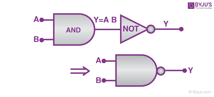
Boolean expression and truth table :
Y=A⋅B¯¯¯¯¯¯¯¯¯¯¯
| A | B | Y′=A⋅B | Y |
| 0 | 0 | 0 | 1 |
| 0 | 1 | 0 | 1 |
| 1 | 0 | 0 | 1 |
| 1 | 1 | 1 | 0 |
(2) The ‘NOR’ gate: From ‘OR’ and ‘NOT’ gate
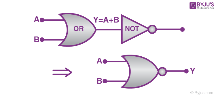
Boolean expression and truth table :
Y=A+B
| A | B | Y′=A+B | Y |
| 0 | 0 | 0 | 1 |
| 0 | 1 | 1 | 0 |
| 1 | 0 | 1 | 0 |
| 1 | 1 | 1 | 0 |
(3) The ‘XOR’ gate: From ‘NOT’, ‘AND’ and ‘OR’ gate.
The logic gate which gives high output (i.e., 1) if either input A or input B but not both are high (i.e. 1) is called exclusive OR gate or the XOR gate. It may be noted that if both the inputs of the XOR gate are high, then the output is low (i.e., 0).
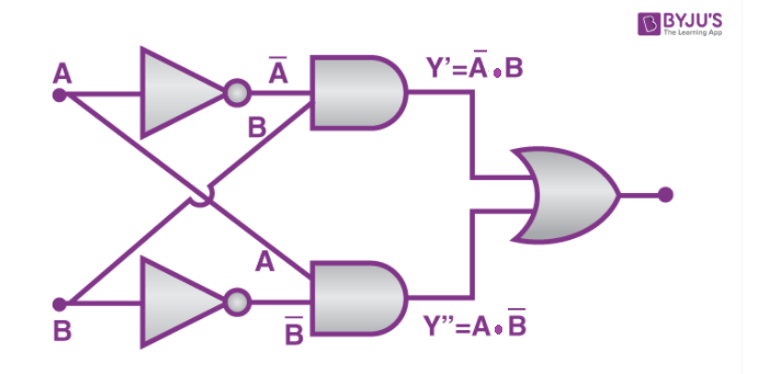
Boolean expression and truth table: [latex]A.\bar{B}+\bar{A}.B[/latex]
or
[latex]Y = A \bigoplus B[/latex]
| A | B | Y |
| 0 | 0 | 0 |
| 0 | 1 | 1 |
| 1 | 0 | 1 |
| 1 | 1 | 0 |
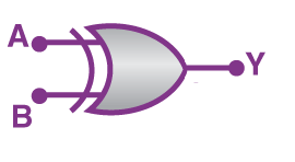
(4) The Exclusive nor (XNOR) gate XOR + NOT
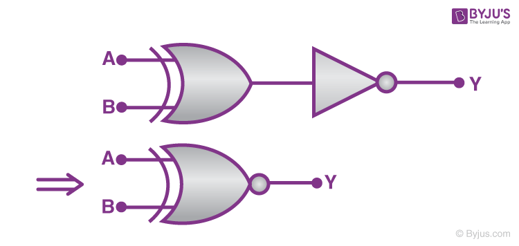
Boolean expression: [latex]Y= \bar{(A\bigoplus B)}[/latex]
| A | B | Output |
| 0 | 0 | 1 |
| 0 | 1 | 0 |
| 1 | 0 | 0 |
| 1 | 1 | 1 |